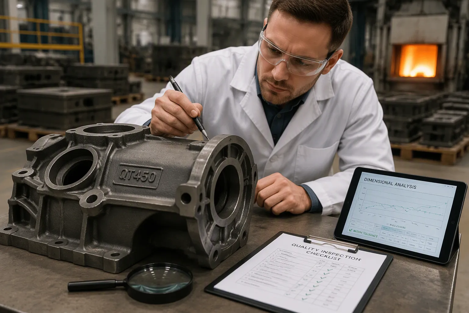
QT450 ductile iron castings most often fail on five defects: shrinkage porosity, gas porosity, nodularity and graphite degeneration, sand inclusion and slag, and cold shuts and misruns. In this long educational B2B industrial blog, each section gives a quick description, the root causes specific to QT450, and practical buyer actions such as specification adjustments, supplier communication, and inspection checkpoints. The defects appear in order of how often they hit QT450 production and how much they cost in scrap, rework, and downtime.
Key Takeaways
- Review riser and gating designs to prevent shrinkage porosity, the most common QT450 defect.
- Control pouring temperature and mold humidity to avoid gas porosity in castings.
- Verify magnesium treatment and nodularity to ensure QT450 castings meet strength requirements.
1. Shrinkage Porosity: The Most Frequent QT450 Defect
How to Spot Shrinkage Porosity on a Received Casting
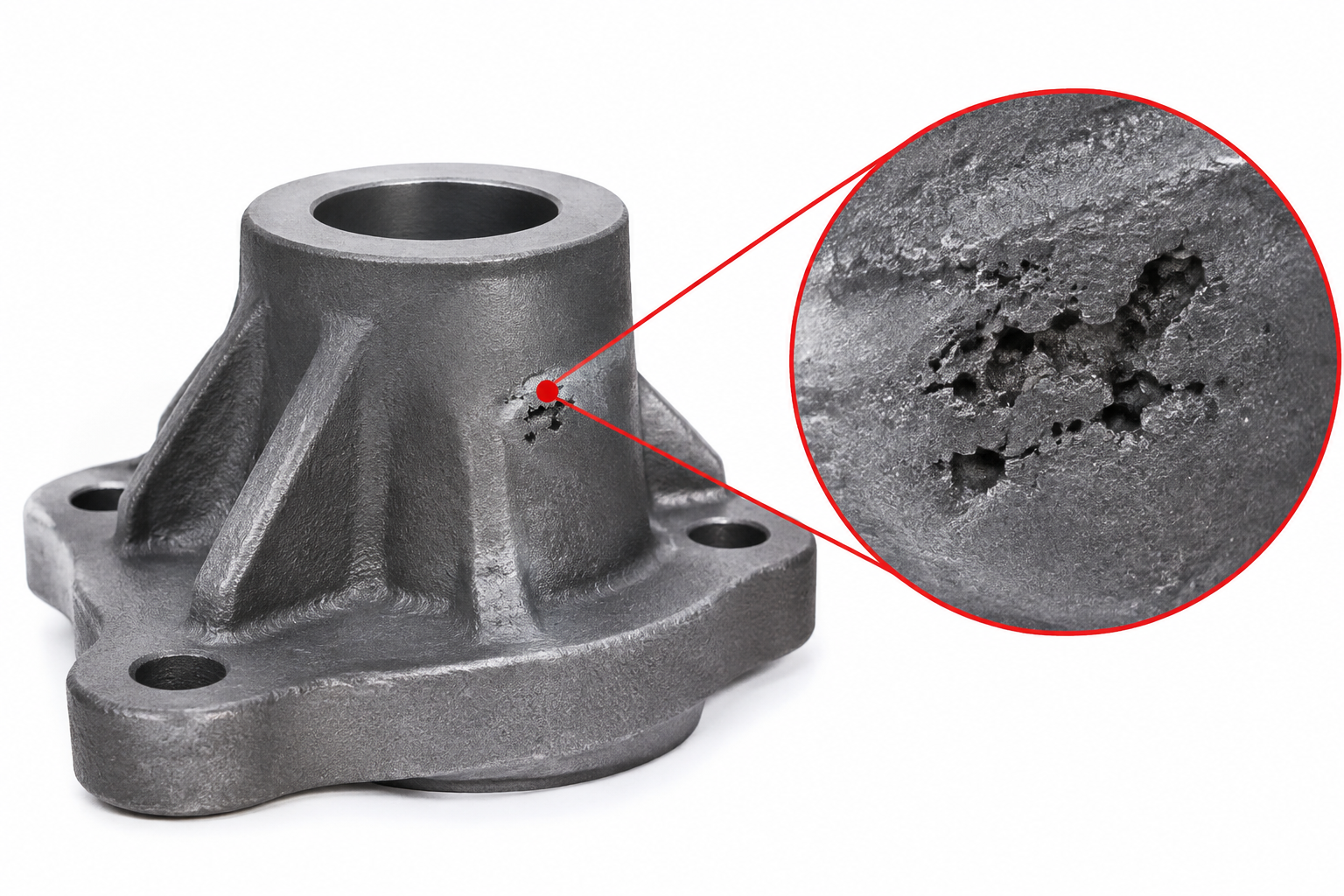
Shrinkage porosity appears as irregular cavities with rough internal walls. These cavities usually sit inside thick sections or near geometric hot spots. A buyer can find them on machined surfaces, X-ray films, or cut sections. The defects often cluster around heavy bosses and side machined holes. In a gearbox housing, for example, shrinkage concentrates in the massive sections around the side machined holes.
Why QT450's Solidification Behavior Causes Shrinkage
QT450 solidifies across a wide temperature range. Liquid shrinkage and solidification shrinkage both demand feed metal. The region that solidifies last, typically the geometric hot spot, cannot receive liquid metal in time. This delayed feeding produces the rough-walled cavities described above. Thick sections cool slowly and remain isolated from the riser. The result is a shrinkage defect that no amount of visual inspection will catch before machining.
Buyer Actions: Riser and Gating Review, Simulation Records, and First-Article Checks
Buyers should request the riser and gating design before approving a production run. Proven design changes reduce shrinkage porosity:
| Design Modification | Effect on Shrinkage Porosity |
|---|---|
| Change to semi-closed and semi-open pouring system | Improved feeding, helped eliminate shrinkage cavity/porosity defects |
| Enlarged risers | Enhanced feeding efficiency |
| Introduction of heated risers | Improved feeding efficiency and prevented isolated liquid zones |
| Strategic placement of oversized risers with innovative riser assembly design | Significantly enhanced feeding efficiency and prevented formation of isolated liquid zones |
Buyers should also ask for casting simulation records and verify hot-spot feeding on the first article. A first-article check with sectioning or radiography confirms the process before mass production begins.
2. Gas Porosity: Trapped Gas from Melt to Mold
How to Tell Gas Porosity Apart from Shrinkage
Gas porosity and shrinkage porosity look similar to an untrained eye. A simple comparison helps buyers sort them out on a received casting.
| Feature | Gas Porosity | Shrinkage Porosity |
|---|---|---|
| Cavity shape | Spherical or elongated, with smooth walls | Irregular, dendritic-shaped |
| Typical location | Within the casting wall or on the surface | Thermal centers (hot spots) of the casting |
| Origin | Entrapped air or gases from mold, moisture, or dissolved gases in the melt | Inadequate feeding during solidification (poor riser design) |
| Relative size and impact | Smaller cavities; reduces load-bearing area and pressure tightness | Often larger and more structurally compromising |
A documented QT450-10 ductile iron valve body case showed leaking gas porosity of φ2–4 mm on the pressure face. Smooth, round cavities on a machined pressure surface point to gas, not shrinkage.
Root Causes: Pouring Temperature, Mold Humidity, and Melt Treatment
Three process variables drive most gas porosity in QT450. Low pouring temperature raises melt viscosity and traps gas before it can escape. High mold humidity releases steam at the metal front. Poor melt treatment leaves dissolved gas and reaction products in the iron. Each cause leaves a different fingerprint, so suppliers should track all three together.
Buyer Actions: Pouring Parameters, Mold Condition, and Supplier Documentation
Buyers can lock down gas porosity with clear process requirements. Specify a pouring temperature window and ask for pyrometer records with each lot. Require sand humidity limits and mold drying checks. Request melt treatment records, including degassing and inoculant details. These documents give buyers a traceable basis for accepting or rejecting a shipment.
3. Nodularity and Graphite Degeneration: The QT450-Specific Risk
What Poor Nodularity Looks Like in Microstructure and Performance
Good QT450 shows isolated graphite spheroids in a ferritic matrix. Poor nodularity shows flake, vermicular, or chunky graphite instead. These shapes cut ductility and impact toughness. A sectioned block with severe degeneration reveals a dark circular center region. There, chunky graphite appears as an interconnected, coral-like aggregate at eutectic cell boundaries, in stark contrast to the desired isolated spheroids. Buyers who skip microstructure checks often discover the problem only after a part cracks in service.
Why Magnesium Treatment and Wall Thickness Drive Degeneration
Magnesium modifies graphite from flakes to spheroids. The residual level matters, and the table below shows the working window.
| Parameter | Value / Effect |
|---|---|
| Residual magnesium range (EN-GJS-450-10) | 0.020% – 0.060% |
| Typical residual Mg after treatment | 0.035% – 0.050% |
| Treatment alloy addition | 0.5 – 1.0% Mg-containing alloy (e.g., FeSiMg) |
| Insufficient residual Mg | Flake or vermicular graphite → reduced ductility |
| Excessive residual Mg | Violent reaction, dross formation, possible carbide promotion |
Magnesium also shifts the eutectic point and widens the liquidus–solidus gap. Thick sections cool slowly and solidify over long times. This combination amplifies undercooling and creates favorable conditions for graphite degeneration. Chunky graphite in heavy sections mainly comes from rare earth segregation at austenite grain boundaries, long solidification time, and lost nucleation sites. Removing rare earths alone is insufficient, because residual interfering elements still trigger degeneration. Adding about 0.015% Sb with a rare-earth-free MgFeSi cored wire fully suppresses chunky graphite and achieves nodularity above 90%. Antimony works through grain-boundary segregation that neutralizes rare earths, reduces carbon diffusivity through the austenite shell, and stabilizes austenite around nodules. A combined strategy of low-RE spheroidizer, controlled Sb at 0.01–0.02%, effective inoculation, and thermal management gives an economical solution for heavy-section ductile iron.
Buyer Actions: Nodularity Percentage Specs, Magnesium Verification, and Test Records
Buyers should write a minimum nodularity percentage into the purchase order, typically 85% or higher for critical parts. They should require residual magnesium verification on each heat and keep the value at the low end of specification. They should also request microstructure test records, including nodule count and graphite shape, with every lot. These three checkpoints catch degeneration before shipment.
4. Sand Inclusion and Slag Defects: Contamination from Mold and Melt
How to Identify Sand and Slag Inclusions on Machined Surfaces
Sand and slag inclusions show up as irregular dark pockets on machined faces. Sand grains look angular and glassy under magnification. Slag appears as a smooth, glassy film or a spongy mass. Both defects interrupt the machined surface and weaken pressure tightness. A buyer who spots a dark pit on a sealing face should request a penetrant test and a section through the area.
Root Causes: Molding Sand Discipline, Gating Design, and Slag Removal
Loose molding sand, weak mold corners, and poor ramming release sand into the metal stream. Turbulent filling stirs slag and sand into the cavity. Poor slag removal during pouring leaves floating slag in the ladle. Gating design offers the strongest lever. Suppliers should apply these principles:
- Use an open pouring system such as bottom pouring to reduce turbulence and avoid slag inclusion and air holes.
- Set up risers and chillers to ensure sequential solidification and avoid shrinkage cavities.
- Strictly control pouring temperature at 1300–1400 °C for cast iron to avoid oxidation and slag inclusion.
Overflow risers near large holes further minimize slag inclusions in valve body castings. A gating ratio of internal runner : cross runner : sprue = 1 : 1.65 : 1.2, calculated for a 360 kg pour weight, controls fill. A pouring time of about 16 s and a minimum sprue area near 22.9 cm² regulate metal flow and reduce turbulence-related slag entrapment.
Buyer Actions: Molding Sand Standards, Cleaning Requirements, and Inspection Criteria
Buyers should write molding sand standards and cleaning requirements into the purchase order. Agreed inspection criteria give both sides a clear acceptance basis.
| Defect category | Inspection method / reference | Acceptance criteria |
|---|---|---|
| Surface sand inclusions & blowholes | Visual / penetrant testing (per GB/T 9444-2020, GB/T 9443-2020 and internal standards) | Defect diameter ≤ 3 mm; single defect area ≤ 10 mm²; spacing between defects on same plane ≥ 50 mm |
| Internal slag inclusions / defects | Ultrasonic testing (UT) | Equivalent defect size ≤ φ2 mm; crack-like defects not permitted |
| Repaired weld zone (surface) | Visual + penetrant testing over weld and 20 mm surrounding area | Weld surface flat, free of blowholes, cracks, slag inclusions; no linear or circular defects allowed |
| Repaired weld zone (internal, key components) | Ultrasonic testing (UT) | No internal defects with equivalent size > φ2 mm |
| Key load-bearing components | Mechanical property testing after repair | Tensile strength ≥ 500 MPa; impact toughness at −20 °C ≥ 15 J/cm² |
5. Cold Shuts and Misruns: When Metal Fails to Fill
How to Recognize Cold Shuts and Misruns
Cold shuts appear as linear seams or rounded, overlapping edges where two metal streams meet but fail to fuse. Misruns leave sections of the mold cavity unfilled, often at thin walls, sharp corners, or the far end of the casting. Both defects show clearly on the raw casting surface. A buyer who sees a seam line on a machined face or a missing edge on a thin rib should flag the lot for review.
Why Pouring Temperature and Section Thickness Matter in QT450
Thin sections lose heat fast, so metal may freeze before the cavity fills. A trial on ductile iron castings lowered the pouring temperature and produced no cold shuts or misruns, which ruled out temperature as the principal cause in that case. Mold venting proved the stronger factor.
| Factor | Condition described | Effect on cold shuts / misruns |
|---|---|---|
| Poor mold venting | Low sand permeability and inadequate venting slowed metal flow and impaired mold filling; molds collapsed even after the pouring cup was full | Misruns and cold shuts occurred, contributing to porosity; mold wall movement further raised shrinkage tendency |
| Low pouring temperature | Tested as a variable in a related ductile iron casting trial | No cold shuts or misruns observed; judged not to be the main cause |
Pouring temperature still matters for thin walls. QT450 castings generally call for a pouring temperature of 1470–1510 °C. A thin-walled QT450-10 metro gear box with 10–12 mm walls ran at about 1500 °C melting and roughly 1400 °C pouring, and that range filled the thin walls without cold shuts.
Buyer Actions: Pouring Temperature Control, Part Design Review, and Process Audits
Buyers should set a pouring temperature window in the purchase order and ask for pyrometer records per lot. A part design review should confirm minimum wall thickness and corner radii before tooling starts. Process audits should check sand permeability and venting practice, since venting failures drive most filling defects.
QT450 defects trace back to five controllable process points. Buyers should focus on riser and gating review for shrinkage, melt and pouring control for gas porosity, magnesium treatment verification for nodularity, molding sand discipline for inclusions, and pouring temperature control for cold shuts. Clear specifications, agreed inspection criteria, and early supplier communication stop most defects before shipment. Buyers should build these checkpoints into purchase orders and first-article approvals, and require production records, inspection reports, and material test records for full traceability.
FAQ
Which QT450 defect should a buyer check first?
Shrinkage porosity deserves the first look. It occurs most often in QT450 production. Buyers should review riser and gating records before approving any lot.
Can a supplier repair a QT450 casting with a defect?
Repair is possible for some surface and internal defects. Buyers should set weld repair criteria in the purchase order. Repaired zones need penetrant or ultrasonic testing before acceptance.
What documents should accompany each QT450 shipment?
Buyers should request production records, inspection reports, and material test records. These documents confirm pouring parameters, magnesium treatment, and microstructure results. They also support full traceability for export shipments.
Buyers who want a practical starting point can share their drawing files and defect history with the engineering team for a process review.
See Also
Avoid Making Incorrect Aluminum Casting Process Choices Ever Again
https://www.xuxiangtaimetal.com
Qingdao Xuxiangtai Machinery